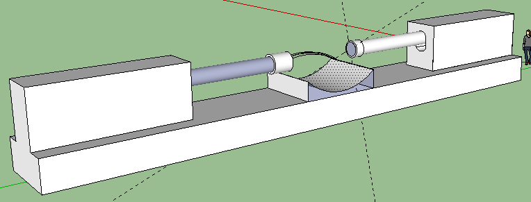
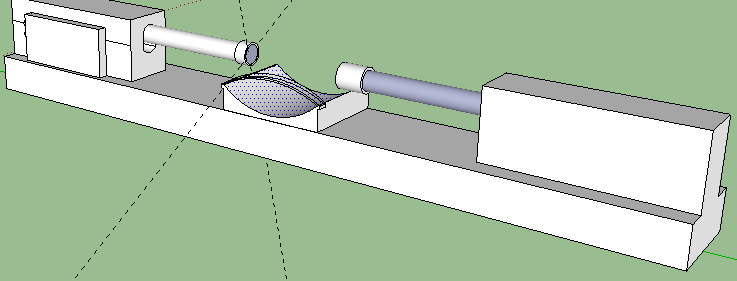
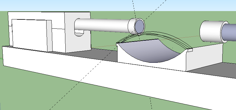
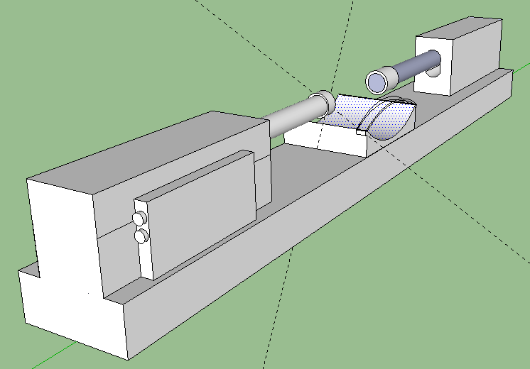
Me: The recent post on Tyler’s HeightQuest HEREabout the fact that Yokota suggested the LSJL technique can be actually be used to lengthen the long bone for adults has sort of made me take the LSJL idea a little more serious. That is why I spent a little bit of time to draw out a 3-D CAD Design of the proposed automatic LSJL machine. I wrote about the idea of building a real LSJL machine/device that is automatic from a previous post entitled”How To Build A Personal LSJL Automatic Device For Less Than $600“.
For you to play around with the 3-D model I built, just click HERE to download the SketchUp File (extension is .skp) and for you to open the file correctly, you’ll need to type into Google you want to download the Google SketchUp 8 software. It is Free. Once you install the SketchUp application, run it and you can open the file. It’s titled “LSJL Automatic Device”.
Considerations: I have used SolidWorks and AutoCad before in my training and school and work. I can learn ProE and 3dsMax in probably 3-4 hours and get a real professional looking drawing design put up with all the specification. I already know the Electrical and Mechanical Engineers and Metal Fabricators who can put this together. The limiting things are the fact that these engineers all have their own life and schedule. The money issue comes in as well since the Engineers I know won’t do this for free and I don’t want to spend an entire weekend learning how to program an Integrated Circuit. The parts would take about 2-3 weeks for them to all arrive. You would need at least 2 people to get the thing done in a reasonable time. One is for programming the servos correctly. This will take about a day to get the program script created to send the right amount of stroke and frequency. Then the programmer has to teach the user of the device how to change the variables in the script to fit for their joint dimensions. It would take another person to put together the parts and fit the parts together in a stable way.
Description: Note the reason for the need for 2 Linear Digital actuators. They will be positioned on a solid support facing each other. You have a resting area for your joints (knees, elbows). There is a strap on the resting area to hold down the joint securely so it does not shift and move around minimizing the loading effects. The FPGA digital board is attached to one of the actuators on the side, although it can be put anywhere desired. The two side knobs connect to a device (laptop) where you program the Board to send certain signals to the actuators to push down at a certain frequency and speed. You want to also leave room vertically for how much distance you would move up and down the actual actuators since each person’s leg and arm epiphysis are in different regions. The hard part will be programming the digital servo to hit the place at the right frequency and speed. Remember that Force or Load is Power/Speed. You have the power ratings for the bought actuators and you know the speed is also provided, so you can figure out what is the maximum load for each stroke length.


Pingback: Natural Height Growth Podcast, Episode 3: On The LSJL Device, Zixia Qigong Method, Lance Ward Review, And Biomedical Growth Research Initiative - Natural Height Growth | Natural Height Growth