Monthly Archives: December 2012

My Research On Wikipedia Looking For Piezoelectric Materials Lead To Dr. Carl Brighton Again!

I think at this point there is a very large amount of evidence that shows that if there is one leading researcher or scientist which can help our cause and give us a lot of assistance and guide to create an alternative way to increase height after growth plate closure, it would be Dr. Carl Brighton from the University of Pennsylvania. Through out my research, I’ve come across this guy at least 4 times now and this latest one shows that he seems to have had an influence on most of the ideas we have looked into (if only superficially so far).

When I was doing research to find the type of piezoelectric material we could put on the loading device to be built, I decided to review my material science knowledge on piezoelectric materials.

As for my educational background, I have a degree in Chemical Engineering with a focus on Material Science And Physics. I took one class where a considerable amount of homework problem sets were focused on doing piezoelectric calculations. Unfortunately I threw away the textbook after the class was over. I had taken the advanced undergraduate class in E & M (Electricity and Magnetism) using the Maxwell Equations with the classic textbook written by Griffiths (3rd ed.) and also glanced through the Berkeley textbook by Purcell and have looked through Feynman’s lecture books as well. I have seen this stuff before.

When I was looking through the Wikipedia article on Piezoelectric Materials there was a subsection dedicated to just Bones, specifically dry bones. I’ll post it below…

Bone

Dry bone exhibits some piezoelectric properties. Studies of Fukada et al. showed that these are not due to the apatite crystals, which are centrosymmetric, thus non-piezoelectric, but due to collagen. Collagen exhibits the polar uniaxial orientation of molecular dipoles in its structure and can be considered as bioelectret, a sort of dielectric material exhibiting quasipermanent space charge and dipolar charge. Potentials are thought to occur when a number of collagen molecules are stressed in the same way displacing significant numbers of the charge carriers from the inside to the surface of the specimen. Piezoelectricity of single individual collagen fibrils was measured using piezoresponse force microscopy, and it was shown that collagen fibrils behave predominantly as shear piezoelectric materials.[15]

The piezoelectric effect is generally thought to act as a biological force sensor.[16][17] This effect was exploited by research conducted at the University of Pennsylvania in the late 1970s and early 1980s, which established that sustained application of electrical potential could stimulate both resorption and growth (depending on the polarity) of bone in-vivo.[18] Further studies in the 1990s provided the mathematical equation to confirm long bone wave propagation as to that of hexagonal (Class 6) crystals.[19]

Me: There was one key phrase that really got me interested in seeing what researchers have found and it was the highlighted one above. This citation, #18, reveals that it was written by Brighton…. What we may need to do right now like detectives is try to track down these papers, get them, and see what is inside them. Tyler’s idea behind the potential inducing from fluid flow idea for LSJL comes directly from these findings from more than 30 years ago.

^ Pollack, S.R, Korostoff, E., Starkebaum, W. y Lannicone, W (1979). “Micro-electrical studies of stress-generated potentials in bone“. In Brighton, C.T., Black, J. and Pollack, S.R.. Electrical Properties of Bone


So I tracked down this paper from PubMed records. This is the link I found. (SOURCE). It seems that the name of the paper is DIFFERENT. It might not even be the same paper since it is missing one of the authors, someone named Lannicone.

J Biomed Mater Res. 1979 Sep;13(5):729-51.

Microelectrode studies of stress-generated potentials in four-point bending of bone.

Starkebaum W, Pollack SR, Korostoff E.

Abstract

A microelectrode technique has been developed to enable the study of stress-generated potentials (SGP) in bone to a spatial resolution of 5 micrometers. The technique has been used to measure the electrical potentials as a function of bone micromorphology in four-point bending. Electric fields ranging from 30 to 10(3) times greater than is measured by conventional macroscopic methods have been discovered at the Haversian canals for human and bovine cortical bone. The amplitude and direction of the electric field in the osteons depend specifically upon the amplitude and the sign (i.e., compression or tension) of the stress. The implications of this finding with regard to the origin of SGP and their possible physiological significance are considered.

PMID: 479219  [PubMed – indexed for MEDLINE]

Me: This next paper could be the other half but still is not of the same name or of the same authors (missing two of them). From source link HERE.

J Biomed Mater Res. 1979 Sep;13(5):753-63.

Microelectrode study of stress-generated potentials obtained from uniform and nonuniform compression of human bone.

Iannacone W, Korostoff E, Pollack SR.

Abstract

By use of a previously developed microelectrode technique, the effect of nonuniform stresses on the stress-generated potentials (SGP) in bone were studied to a resolution of 5 micrometers. Comparison was made between uniformly and nonuniformly applied compression of human cortical bone. It was found that the radial electric fields for osteons in a specimen under uniform compression were equivalent, and such specimens possessed no macroscopic SGP; for nonuniform compression, the electric fields of osteons differed, and a macroscopic SGP was measured. The magnitude of the macroscopic SGP thus appears to be dependent upon local stress differences and, hence, on the SGP of local regions.

PMID: 479220    [PubMed – indexed for MEDLINE]


The Project Proposal BY Zhang FOr IGF-2 Injections And Load Driven Bone Lengthening, What Happened With The Results?

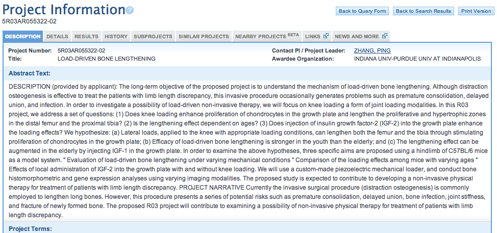
Me: From a reader of the website Sugata Negi (thanks man) he provided me with a link to a proposed experiment Zhang did in 2009 looking at the specific nature of the possibility of lengthening bone entitled “LOAD-DRIVEN BONE LENGTHENING” . We see that the project finished in May 2011 and there was no results published on what happened on the results section. This suggest that Zhang already knows the results and haven’t published his findings yet to PubMed. If the results are positive with this research project, then I will definitely go back to the US to get the device built for humans. There is so much potential for this biomedical device to change the lives of children throughout the world. Even if this thing can’t work for adults, we can still use it for young kids and make a huge difference while possibly make some good profit too. What is really the most interesting part is the section under the “Similar Projects” tab.

Implications: What we see is that many of the ideas and topic we have looked at before are already in this database. We can see who are the top researchers in this field and which professors in the world who are doing the type of research we really need help with. There is a select few that will be critical to help us or guide us if we can get their assistance. We find People like Robert Ballock, Clifford Tabin, and as always Dr. Carl Brighton. His name and association is HUGE in this field. If I can get an interview with him for the podcast it will definitely be the greatest coupe and push in real breakthrough for this website ever.

Resolving The Frequency And Loading Problem For The LSJL Device Using Elementary Physics

So I had said before on video and on the podcast that I had rouble understanding how to reach the right high values in Force applied and also the right high frequency for the loading to be dynamic. I had thought that there had to be some tradeoff between the two since most devices you find can’t reach those values like from Progressive Automations.

From the videos on the Progressive Automations you realize the large, heavy powered Actuators which extend or retract by a DC power moves and strokes rather slowly never reaching even the 5 Hz value we saw in the studies with either the rat hindlimbs or the rat elbows which causing humeral and ulna lengthening. I was thinking about this problem last night when I realized what was the problem, and the issue was that I was probably rethinking about the original loading device using by Yokota and Zhang in an incorrect way.

Here is how we can resolve the Loading Vs. Frequency problem. We have to reduce the frequency down to a certain level maybe 1 Hz for the device to even allow for load.

From the progressive automations website, we see that the usual types of applications of the linear servos was to hold something up, like a 48″ TV. When you want to hide a tv in a dresser, you click on a remote and the actuator moves down and the TV drops down out of sight. When you want the TV, you hit another button and the actuator pushes the TV back up. This is how the actuators are supposed to work, by providing a constant, static (NON-DYNAMIC) loading value.

Assuming the TV is 100 lb, then the mass of the TV is calculated to be around 100/2.2= 45.36 kg. That is the mass of the TV. remember that the units of lb and kg are completely different, one is for a fundamental intrinsic property while the other is for a derived function depending on the environment, specifically the gravitational force the mass exerts at a certain direction. In SI units it is 9.81 m/s^2 while in US units it is 32.2 ft/s^2. For the actuator to push the TV up, it’s loading which is a force value in units of Newtons (kg*m/S^2) must be higher than the force of the TV pushing down on the actuator, which is just it’s weight.

These conceptual understanding shows that for the LSJL machine to even have a loading value in units of force, Newtons, it must hold at least for a extended time, of a static constant value.

The reason is because to calculate the vector function F we must have a mass, which is easily found, and another function, acceraltion which is a vector so we have to get the direction as well.
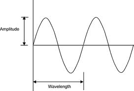
Taking a short tangent into waves and vibration elementary physics we remember that we can treat the dynamic movement of one of the clamp ends as a ossilator which ossilates between the middle set point moving between a set distance away from the middle set point, (say 3 cm in -x and x direction) in the imagined arbitrarily assigned x-y-z axis system. We say that when this simplied system of an ossicilator is modeled using simple mathematics.

It can also be viewed as a pendulum system if desired but an ossilator is a more accurate model. The distance the peizoelectric load side moves if graphed on just a x-y axis plane where the x is time and y is distance, would be a sine wave since we assume the position of the side starts from the initial set point (value of zero). So the value of the distance versus time looks like the figure on the right.

For us to go from distance to acceleration, we have to take the derivative of the x=f(t) function twice. is a=del^2(x=f(t)/dt^2

If we remember from calculus, the derivative of the sine wave is the cos wave. but when we take the derivative of the cos wave we get back to the sine wave. This shows that at certain times of the dynamic moving loading device, it has no acceleration, specifically when the flat piezoelectric plate which is the clamping side is at the set point. which means the force it is applying is really 0, so there is no loading.

Conceptually that means that when the clamping moving in a sinusoidal, oscillatory movement reaches the bone to hit it, it is at its greatest value of acceleration in terms of magnitude. That means that if we increase the frequency speed in units of Hz, we should increase the loading value at the point of contact. The key is to make sure the piezoelectric material in contact with the epiphysis/bone is a hard material that has a high young’s modulus which will not deform. The impact of the hit

The main problem conceptually now is where we are really supposed to clamp or not. When talking about units in Hertz, the real physical units are “the rate of the occurence or phenomena over a specific time duration, 1 second”. When in the Articles Zhang says they had 5 Hz (Source) that means the the device hit the mouse synovial joint 5 times in one second. From a picture of the device, it seems that the device is not automated with some form of feedback loop device. It was probably operated on by a graduate student who had to clamp down using their hands.

From the PubMed study entitled “Elbow loading promotes longitudinal bone growth of the ulna and the humerus” by Yokota and Zhang I took a clip of the picture below which shows the schematic of the original device used for loading. Also took the section titled “experimental design”
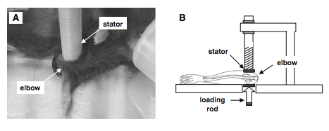
Experimental design

In the loading group, mice were mask-anesthetized using 1.5% isoflurane and received loads to the left elbow in the lateral-medial direction with the custom-made piezoelectric mechanical loader. Loads were 0.5 N at 5 Hz and given for 5 min per day for 10 days (Fig. 1a, b). The lateral and the medial sides of the ulna and humerus were in contact with the loading rod and the stator, respectively.
We chose a forelimb configuration that made the right angle (90) between the ulna and the humerus, since in this position the forelimb was relaxed and stably immobilized (Fig. 1c). To position the elbow properly for loading, the lower end of the loading rod and the upper end of the supporter (nylon screw) were designed to form a pair of semi-spherical cups. The olecranon process and coronoid process of the ulna together with the ulnar tuberosity, and medial and lateral epicondyles of the humerus were confined in the cups. The tip of the loader had a contact surface of 3 mm in diameter. To avoid a local stress concentration between the elbow and the loader, both the loading surface and supporter were covered with silicon rubber. The right elbow was used as a sham loading control (contralateral control), which was placed under the loader with no dynamic loading. In the age-matched control group, the same procedure was applied without application of lateral loads.

I was introduced to this Patent Idea HERE when I first proposed building this device which showed that the University researchers had in 2005 already filed a patent. In the patent Yokota with Tanaka stated that …”The magnitude of the mechanical load is oscillated and is applied periodically for a short durations of time.” This suggests that the oscillatory movement is not the easily mathematically graphed behavior of sinusoidal functions like using a sine or cosine function. It seems that the device is supposed to be applied to the bone, held in that position for a short while and then removed, and the processes repeated. This would make more sense since we saw from HeightQuest that the procedure involves using a C-Clamp and holding the clamp position for about 30 seconds before letting go and doing it for only about 5 minutes.

Me: From the Description section of the patent we find that  they describe the patent using these figures. So these are the proposed values for the device to be built.

  • Frequency: 2 Hz
  • Load: 100 Newtons laterally
  • PiezoElectric Material Used: Electrochemical materials such as a polypyrrole polymer and a polythiophene polymer can be used as an artificial-muscle-like actuator
For mice… Frequency: 2 Hz, Loading: 0.5 Newtons, 
Interesting, the big problem now is that I don’t know how or which equation to use to calculate the force of that will be generated from the type of device we will build. In the testing, the equation they used is sigma*w*t. The device proposed involves a motor that moves in rotation like the piston you see in the wheels of old style trains which have an overall 1 dimensional movement created from rotational energy. This proposed patent for a device is a feedback mecahnism with a way to tell teh device how much force to use at what frequency as well as collect the amount of electrical energy and potential as well as force loaded down in data form for analysis later. At this point, I have not read over the entire patent but the device is quite advanced and sophisticated enough that I would need at least 2 electrical engineers to put everything together within a reasonable time frame if we just tried to use the principles of the device themself.
Implications: This post shows that I was too naive and optimistic in thinking that building a LSJL device for human use would be easy because I had not considered the effect of also the piezoelectric material for electrical stimulation utility. What I have finally concluded at least at this point is that the 5 Hz that Yokota or Zhang was talking about was probably for per minute basis than per second. Hz is supposed to be for per second basis, but if we consider the fact that the oscillating loads were only done for about 5 minutes a day and that there was only 5 Hz used, that meant one loading and removal took 1 minute each. This would coencide with the LSJL method Tyler proposed which is to clamp down on the bone for 30 seconds, let go for another 30 seconds, and repeat the process. At this point, it would suggest that we do not need a frequency of 5 Hz but actually 1/60 or about .016 Hz. The loading is also very small at the suggested level of 100 Newtons. All I can conclude after this long post is that we will need to really sit down to do the right types of calculations to figure out the values for how to load the bone, how big the area of the piezoelectric device must be, and whether we should set up a type of recording and feedback system to the device to optimize for efficacy.

32, 132 and the torque applied to the band 228, 328 around joint 22 can be chosen so that fluid flow would be induced in bone without disturbing any function or structure of joint 22. For apparatus 20, 122 that may be driven by air pressure approximately 40 kPa (5.8 psi) was needed to provide 0.5 N to murine elbows in the second exemplary study discussed below. Assuming that 100 N is used to press a lateral wall of a human knee joint, 51 kPa (7.4 psi) is required for a 50 mm in diameter bladder 32, 132. For instance, pump 136 may be a micro air pump driven at 6-24 NDC with 180 g weight (available from Sensidyne, of Clearwater, FL). 

For apparatus 220, 320 driven by tensioning the circumferential band 228, 328, FIGS. 1 C and ID, the tensile stress in the band, σt, is:  σt = Pr/t  where P = pressure, r = radius of a supporter, and t = thickness of a band. With P = 51 kPa, r = 50 mm, and t = 3 mm, σt is estimated as 0.85 MPa. Since the required force to induce σ , is σtwt with w = width of a band 228, (50 mm), motor 236 with 5-mm torque arm needs to generate about 0.64 Νm. For example, a gear motor (3363020, available from Igarashi Motors, of St. Charles, IL) having dimensions of 20 mm x 24.5 mm x 29 mm (110 g) can generate up to 1.0 Νm at 12 V. 

Electrochemical materials such as a polypyrrole polymer and a polythiophene polymer can be used as an artificial-muscle-like actuator 328 for apparatus 320. These polymers can be stretched or compressed through ?on formational changes inducible in an electrical field. Actuators can be formed in any shape, for example, belts, and it can easily generate strain of 10 % and stress above 20 MPa with a small amount of electricity. For example, a conductive polypyrrole polymer (available from EAMEX Co., of Osaka, Japan) with a cross-sectional area of 50 mm (width) x 3 mm (thickness) can generate 189 Ν (Hara, S, Zama T, S S, Takashima W, Kaneto K. 2003. Highly stretchable and powerful polyprrole linear actuators. Chemistry Letters, 32:576-577.). 

A first exemplary experimental study compared bone formation in murine ulnae exposed to mechanical loading with bone formation in nonloaded control murine ulnae. Twenty female C57BL/6 mice (14 weeks old) with a body weight of approximately 20 g were used for the study. Each mouse was mask-anesthetized using 2% isoflurane. The mechanical loading was applied with piezoelectric loader 400 (FIGS. 4A and 4B) to right arm 402a (See, Tanaka, S.M., Alam, I.M. and Turner, CH. (2003) Stochastic resonance in osteogenic response to mechanical loading. FASEB J, 17, 313-314.) for 3 minutes per day for three consecutive days to elbow 408 through a lateral medial direction as shown in FIG. 5 A. Left arms were used as nonloaded control specimens. Loading force 416 was sinusoidal at 2 Hz with a peak-to-peak force of 0.5 N, as shown in FIG. 8A. In order to avoid local stress concentrations between joint 408 and loading element 414, the surface of loading element 414 was covered with a silicon rubber sheet (not shown). 

The exemplary mechanical loader 400 used for the study includes an electro-mechanical loading structure and instrumentation. Specifically, structure 430 supports loading element 414 and cantilever 446, coupled to structure 430, supports loading screw 412. Loading screw 412 has an adjustable displacement relative to loading element 414. Specimen 402 to be loaded is positioned between screw 412 and element 414 and screw 412 is adjusted to contact specimen 402. Data acquisition board/command generator 436 provides a command signal to piezo driver 434, which in turn drive piezoelectric actuator 432. Actuator 432 is mechanically coupled to loading element 414 and provides the desired mechanical load commanded by command generator 436. 

Instrumentation of mechanical loader 400 includes strain gauge 444 mechanically coupled to cantilever 446 and electrically coupled to strain gauge conditioner 438 and data acquisition board 436. Strain gauge 444 provides monitoring and control of the mechanical load applied to the specimen. Displacement sensor 448 is coupled to cantilever 446 and measure the variation in displacement relative to lever 450 coupled to loading element 414. Switch 442 selectively electrically couples data acquisition board 436 to signal conditioner 440 which is electrically coupled to displacement sensor 448. Switch 442 also selectively electrically couples data acquisition board 436 to electrode 452. Electrode 452 is placed in contact with specimen 402 for measuring the electrical potential of specimen 402 relative to the ground of loader 400. 

All mice were, given an injection of 0.05 ml saline containing 1% calcein 2 and 6 days after the last application of mechanical load, and ulnae 404a/b were harvested 13 days after the loading. Harvested ulnae 404a/b were fixed in 10% formalin for 2 days. After dehydration by immersion in a series of efhanol solutions, ulnae 404a/b were embedded in methyl methacrylate. Transverse sections 405a/b (FIGS. 6A-6C) 50 um in thickness were cut at 2.5 mm distal from elbow 408 using a diamond wire saw, and ground with sand paper (#400) to about 20 um in thickness. The sections were examined with a fluorescence microscope. 

Using a semiautomatic digitizing system (Bioquant available from R&M Biometrics, of Nashville, TN), three morphometric parameters were determined for the periosteal surface of ulnae 404a/b, including mineralizing surface (MS/BS, %), mineral apposition rate (MAR, um/day), and bone formation rate (BFR/BS, um3/um2/year), where MS = sum of the length of the double-labeled perimeter and half of the single-labeled perimeter, BS = total length of the perimeter, MAR = average radial distance 418 (FIG. 6C) between the two labels per day, and BFR = MS/BS x MAR x 3.65 (Hsieh, Y.F. and Turner, CH. (2001) Effects of loading frequency on mechanically induced bone formation. Journal of Bone and Mineral Research, 16: 918-924). 

Streaming potentials were measured as a voltage generated between electrode 452 on a periosteal surface of an ulnar midshaft and a common ground for loading system 400. The periosteal surface connected to the electrode was dissected free of muscle and was always kept moist with a saline solution. A 16-bit data-acquisition board operated by a computer was used to record streaming potentials at a 250-usec interval. In order to examine statistical significance in the histomorphometric data, ANOVA analysis (using Statview, Version 5.0, available from SAS Institute Inc., of Cary, NC) was conducted with a significance level at p < 0.05. 

Bone histomorphometry with fluorescent cacein-labeling revealed that elbow loading significantly stimulated bone formation. Cross section 405a (FIGS. 6B and 6C) of ulna diaphysis 2.5 mm distal (16% of ulnar length) to elbow 408, clearly showed double labeling 418 on a periosteal surface with a sinusoidal loading for 3 minutes per day for 3 days on the elbow, as compared with cross section 405b of unloaded control ulna. Three bone morphometric parameters, MS/BS (mineralizing surface, p=0.0002), MAR (mineral apposition rate, p=0.045), and BFR/MS (bone formation rate, p=0.012), were significantly increased by elbow loading , as shown in FIGS. 7A-7C. The increase in MS/BS, MAR, and BFR/MS was 3.2-fold, 3.0-fold, and 7.9-fold, respectively. 

Streaming potential, induced by a coupling between ion flux and fluid movement, is a good indicator of strain-induced fluid flow in bone (Beck, B.R., Qin, Y.X., McLeod, K.J., and Otter, M.W. (2002) On the relationship between streaming potential and strain in an in vivo bone preparation. Calcif Tissue Int, 71, 335-343). In response to joint loading at 2 Hz with 0.5-N force, harmonic potentials were observed that were synchronized with the mechanical stimuli, as shown in FIGS. 8A-8C Longitudinal axis loading to ulna 404b, shown in FIG. 5B, one of the conventional bone loading methods to induce strain in cortical bone and bone formation (Tanaka et al., 2003; Robling, A.G. and Turner, CH. (2002) Mechanotransduction in bone: genetic effects on mechanosensitivity in mice. Bone, 31, 562-569), also generated a streaming potential with a magnitude on the same order as lateral joint loading (FIG. 5 A). The histomorphometric data demonstrates that lateral joint loading requires a lower magnitude of loading force (0.5 N peak-to-peak) to induce bone formation than the conventional axial bone loading methods which requires over 1 N peak-to-peak force (Robling et al., 2002). 

Conventionally a joint has been considered as a shock absorber that protects bone from impact loading (Voloshin, A., Wosk J., Brull M. 1981. Force wave transmission through the human locomotor system. J Biomech Eng, 103:48-50). In the first exemplary study, however, joint loading showed a significant increase in bone formation on a periosteal surface of diaphysis cortical bone. It has been well-recognized that the osteogenic responses can be induced by bone strain in vivo (Rubin, C.T. and Lanyon, L. E. (1985) Regulation of bone mass by mechanical strain magnitude. Calcified Tissue International, 37:411-417; Turner, C. H., Forwood, M. R, Rho, J. Y., and Yoshikawa, T. (1994) Mechanical loading thresholds for lamellar and woven bone formation. Journal of Bone and Mineral Research, 9:87-97) and fluid flow in vitro (You, J., Yellowly, C. E., Donahue, H. J., Zhang, Y., Chen, Q., and Jacobs, C. R. (2000) Substrate deformation levels associated with routine physical activity are less stimulatory to bone cells relative to loading-induced oscillatory fluid flow. Journal of Biomedical Engineering, 122:387-393). Since streaming potential is an indicator of fluid flow in bone, the data on streaming potentials and bone morphometry demonstrate that joint loading can induce fluid flow and stimulate bone formation without causing strain in cortical bone

Combining Growth Factors TGF-Beta1 And IGF-1 With Dynamic Deformational Loading On Chondrocyte Implanted Hydrogels

Me: This article talks about what was seen when you take two of the most common growth factors TGF-Beta1 and IGF-1 and use them in conjunction with dynamic deformational loading application on hydrogels which are embedded with chondrocytes. Like with a recent post where three patents were analyzed with the idea that you take the chondrocyte in gel form and get that implanted into articular cartilage knee defects and use them to fill up the cartilage this mixture can be used instead of just growth factors. The application of dynamic deformational loading has already been shown to get chondrocyte implanted into hydrogels to cause expansion in volume size.

Note that in normal epiphyseal growth plate cartilage, there is two main components in the cartilage matrix.

  1. Proteoglycan – (these two parameters or variable increase with using either growth factor or loading but increased more with them combined)
  2. Collagen Type II
We also have something called the equilibrium aggregate modulus. From research and other sources (HERE) it is a term that is calculated taking into account values for thickness, permeability, and the compressive modulus. The equilibirum aggregate modulus is really sort of a way to measure the strength, durability, and viscosity of a cartilage element (or something like that. Not completely sure right now).
What is clear from the results is that if you try to use the growth factors alone, they have the effect of increased values for all three parameters. If the dynamic loading is applied, the three values also increase. When you combine the growth factors with the dynamic load the effect is synergistic with a combined effect. The values for the aggregate modulus seem to increase by almost by about 2.5X value.

Implications for height increase: The researchers said at the end that..“These results support the hypothesis that the combination of chemical and mechanical promoters of matrix biosynthesis can optimize the growth of tissue-engineered cartilage constructs.” What this means that when we do get the LSJL device built, it would be smart to combine it with also growth factors TGF-Beta1 and IGF-1 for maximum effect. To do this for a height increase application, we could just take thick needles and make injections of the two growth factors directly into the long bone epiphysis and then get the LSJL device to dynamically load the epiphysis treating the epiphysis as the hydrogel with chondrocytes encapsulated. We have already proven that lateral dynamic loading on the bone will cause the MSCS inside to differentiate into chondrocytes. Maybe just these two parts is enough but if it is not as effective as hoped, we can add the initial step of injecting hydrogels embedded with chondrocytes first into the epiphysis to begin with through the side, then add the growth factors, and then the loading using the LSJL device. These would allow an initial seed of chondrocytes aggregate to start with and any chondrocyte that results from the growth factor injections or LSJL device loading will layer on top and aggregate with the initial seed after the hydrogel dissolves.


From Link HERE… (Full article on links below)

Synergistic Action of Growth Factors and Dynamic Loading for Articular Cartilage Tissue Engineering

To cite this article:
Robert L. Mauck, Steven B. Nicoll, Sara L. Seyhan, Gerard A. Ateshian, and Clark T. Hung. Tissue Engineering. August 2003, 9(4): 597-611. doi:10.1089/107632703768247304.

Published in Volume: 9 Issue 4: July 9, 2004

Author information

Robert L. Mauck, MS – Department of Biomedical Engineering, Columbia University, New York, New York.

Steven B. Nicoll, PhD – Department of Biomedical Engineering, Columbia University, New York, New York.

Sara L. Seyhan, BS – Department of Biomedical Engineering, Columbia University, New York, New York.

Gerard A. Ateshian, PhD – Department of Biomedical Engineering, Columbia University, New York, New York.

Clark T. Hung, PhD – Department of Biomedical Engineering, Columbia University, New York, New York.

ABSTRACT

It has previously been demonstrated that dynamic deformational loading of chondrocyte-seeded agarose hydrogels over the course of 1 month can increase construct mechanical and biochemical properties relative to free-swelling controls. The present study examines the manner in which two mediators of matrix biosynthesis, the growth factors TGF-β1 and IGF-I, interact with applied dynamic deformational loading. Under free-swelling conditions in control medium (C), the [proteoglycan content][collagen content][equilibrium aggregate modulus] of cell-laden (10 × 106 cells/mL) 2% agarose constructs reached a peak of [0.54% wet weight (ww)][0.16% ww][13.4 kPa]c, whereas the addition of TGF-β1 or IGF-I to the control medium led to significantly higher peaks of [1.18% ww][0.97% ww][23.6 kPa]C-TGF and [1.00% ww][0.63% ww][19.3 kPa]C-IGF, respectively, by day 28 or 35 (p < 0.01). Under dynamic loading in control medium (L), the measured parameters were [1.10% ww][0.52% ww][24.5 kPa]L, and with the addition of TGF-β1 or IGF-I to the control medium these further increased to [1.49% ww][1.07% ww][50.5 kPa]L-TGF and [1.48% ww][0.81% ww][46.2 kPa]L-IGF, respectively (p < 0.05). Immunohistochemical staining revealed that type II collagen accumulated primarily in the pericellular area under free-swelling conditions, but spanned the entire tissue in dynamically loaded constructs. Applied in concert, dynamic deformational loading and TGF-β1 or IGF-I increased the aggregate modulus of engineered constructs by 277 or 245%, respectively, an increase greater than the sum of either stimulus applied alone. These results support the hypothesis that the combination of chemical and mechanical promoters of matrix biosynthesis can optimize the growth of tissue-engineered cartilage constructs.

Vascular Endothelial Growth Factor, VEGF Inhibits Bone Morphogenetic Protein, BMP-2 Expression In Mesenchymal Stem Cells (Important)

Me: Let me first just post the conclusion first from the researchers..

“In the current study we hypothesized that increased expression of both BMP2 and VEGF-A to a tissue-engineered construct seeded with MSCs would augment osteogenesis and angiogenesis. We focused onVEGF-A as this is the major proangiogenic isoform.21 Interestingly, we found that codelivery of these growth factors requires optimization as VEGF potently inhibited BMP2 expression. Conversely, BMP2 had little effect on VEGF expression. The inhibition of BMP2 expression by VEGF occurred at the RNA level, and VEGF inhibited the expression of endogenous BMP2 as well as adenovirally delivered BMP2. The latter finding suggests that VEGF inhibition occurs independently of the BMP2 promoter since the adenoviral gene expression was driven by a constitutively active promoter. Taken together, our findings suggest that approaches utilizing concurrent delivery of growth factors require optimization of growth factor concentration.”

Implications for height increase technology: I think it is very clear that unlike what I and many other researchers thought previously we can’t just combine growth factors together without looking at concentration, density, and percentages in mixtures and expect such growth factor compounds to work synergistically. While the VEGF may have bone modulating properties, when combines with BMPS it may inhibit BMPs and that may be the real way it controls bone growth in vivo. In the paper they hypothesis from teh results that it may be VEGF which is one of the causes for endochondral ossification and caus ethe vascularization of the cartilage for real bone cell stacking leading to height increase. If this is the case, then VEGF operates almost in the opposite effect as the Chondromodulin we researched in recent previous posts. Besides decreasing the estrogen levels in the teenagers body or pluggin up the estrogen receptor alpha and beta in the growth plates, we might be able to also manipulate chondromodulin and VEGF to increase and decrease respectively to slow down the ossification coversion process of what is left of the cartilage in the growth plates.

Also, we know that BMP-2 leads to chondrogenesis as well as osteogenesis and we are focused on differentiating those MSCs towards chondrocytes. If we can help in anyway to prevent the MSCs from differentiating into the osteoblasts and only allow for conversion into chondrocytes and chondroblasts we just might be able to eventually cause enough cells in the intermedullary cavity of the epiphysis to result in newly formed growth plates from chondrocyte aggregation. With enough time, maybe even the cell apoptosis and formation cycle using osteclasts to remove old cell waster may allow for an entire section of the bone to be replaced by chondrocytes. This would indeed prove the ultimate path towards growth plate regeneration and validate the theory on why LSJL would even work to make people taller.

From the paper…

“…several factors limit this technique from becoming routine in clinical practice. One of the biggest obstacles to the use of tissue-engineered constructs in reconstruction of tissue defects is the lengthy culture and manufacturing periods required by conventional techniques. For instance, the synthesis of a tissue-engineered bone construct usually requires a 6–12 week culture and seeding period.”

“The use of exogenous growth factors may be a means by which tissue-engineered construct synthesis and vascularization can be accelerated. Bone morphogenetic proteins (BMPs) may be a method by which osteogenesis can be enhanced in a tissue-engineered bone construct since these growth factors are known to promote osseous repair in endochondral and membranous bones.12–14 BMPs are critical for successful fracture repair and bone development, and exogenous delivery of BMP can induce bone formation in critical-sized bone defects.15,16 Thus, genetic manipulation of cell-seeded MSC constructs with BMP may represent a viable method to accelerate or augment bone deposition

Similarly, delivery of angiogenic growth factors, such as vascular endothelial growth factor (VEGF), may be a means by which vascular ingrowth can be augmented since these molecules regulate angiogenesis. Further, several studies have shown that angiogenesis and osteogenesis are synergistic.17–20 Thus, genetic modification of cell seeded constructs with VEGF may augment vascular ingrowth and osteogenesis in a tissue-engineered construct, thereby accelerating construct synthesis and angiogenesis.”


From Pubmed study link HERE… (This link  has the full article)

Tissue Eng Part A. 2010 February; 16(2): 653–662.
Published online 2009 October 28. doi:  10.1089/ten.tea.2009.0426
PMCID: PMC2947933

Vascular Endothelial Growth Factor Inhibits Bone Morphogenetic Protein 2 Expression in Rat Mesenchymal Stem Cells

Björn H. Schönmeyr, M.D., Marc Soares, M.D., Tomer Avraham, M.D., Nicholas W. Clavin, M.D., Fredrik Gewalli, M.D., Ph.D., and Babak J. Mehrara, M.D., FACScorresponding author
Author information ► Article notes ► Copyright and License information ►
This article has been cited by other articles in PMC.

Abstract

Introduction: While several studies report that bone morphogenetic proteins (BMPs) and vascular endothelial growth factor (VEGF) can act synergistically to improve bone tissue engineering, others suggest that VEGF inhibits osteogenesis. The purpose of these experiments was therefore to evaluate the effect of dual transfection of these growth factors and potential mechanisms of interaction on gene expression and osteogenesis in vitro and in vivoMethods: Marrow-derived mesenchymal stem cells (MSCs) were exposed to recombinant VEGF protein or transfected with adenoviruses encoding BMP2,VEGF, or LacZ in a variety of ratios. Alterations in gene and protein expression in vitro as well as bone formation in vivo were assessed. Results: MSC exposure to AdV-VEGF or recombinant VEGF inhibitedBMP2 mRNA expression, protein production, and MSC differentiation. Coculture experiments revealed that BMP2 suppression occurs through both an autocrine and a paracrine mechanism, occurring at the transcriptional level. Compared to controls, cotransfection of VEGF and BMP2 transgenes prevented ectopic bone formation in vivoConclusion: VEGF is a potent inhibitor of BMP2 expression in MSCs, and supplementation or overexpression of VEGF inhibits osteogenesis in vitro and ectopic bone formation in vivo. Strategies to utilize MSCs in bone tissue engineering therefore require careful optimization and precise delivery of growth factors for maximal bone formation.

Review, Another Look At A-Grow-Bics With Pierre Pozzuto And Why It Might Really Work In Increasing Height

Yesterday I got a email message sent through the company email account where they forwarded a link where the article was about Pierre Pozzuto and his A-Grow-Bics program in London. Now I have already looked at this guy and his claims in a very recent post entitled “A-Grow-Bics Class With Fitness Trainer Pierre Pozzuto Of Fitness Chain Gymbox Claims To Increase Height Through Microfractures“.

At the conclusion of the previous post I had said that it was difficult to say with confidence that this guy can really help adults grow taller. The one source I was using was an article written by a reporter who tried out Pozzuto’s program for only one day and did not see any increase in her height after she went through the intense training and stretching. Of course the claim was always that the person would see at least a height increase of 2 cm or more after doing the program for 6 weeks or they will get their money refunded. Overall, I did the research and saw that this Pozzuto guy was the real deal and he was a licensed physical trainer based in the UK. This article was from the DailyMail UK. It seems this reporter tried out the program too and she noticed a height increase of 2 inches or 4.9 cm to be more exact.

So what is in the program?

“This revolutionary exercise system blends elements of Pilates, Yoga, cardio exercises and stretching moves; it involves hanging upside down like a bat . . . oh, and being strapped on to a rack…”

It seems there is 7 main parts which goes in this sequence…

  1. You first hang on a bar for an extended amount of time, over 30 secs.
  2. You get you ankles locked on bar and you are hoisted up and hanging upside down. You than are to try to reach for your ankles and this strengthens core muscles.
  3. You get on the ground on your stomach and alternate your limbs to strengthen the core muscles and stretch out.
  4. There is an exercise called the “Superman” using cords. Don’t really know what is going on.
  5. You do high intensity jumps on boxes as much as possible to increase HGH production levels.
  6. You then get on a treadmill to do short sprints at the top speed to increase HGH production levels. This is also where the idea of microfractures come in.
  7. You then go to the “rack” which holds the body down with clamps to the wrist and ankles and stretch the spine.

In terms of duration, it was stated..”The whole workout took just under one hour, and Pierre and I went through the same routine once a week for six weeks. I was also given ‘homework’, which involved a few stretches and Pilates exercises,...”

Quote..

  • “Participants are measured at the beginning, and again after every session. There was nothing to show for my effort after week one or week two.
  • But at the end of week three, I’d grown 0.8cm; by week four, I’d grown 2cm; and by the end of the course I had become an astonishing 4.9cm taller.
  • I was stunned, and even Pierre had to measure me twice before we both believed it: six weeks ago, I was 160.5cm (5ft 2in); now I’m 165.4cm (5ft 4in). “
We see that this reporter was a person who stuck it out through the entire 6 weeks unlike the other reporter who didn’t see any results after the first day. This obviously makes more sense thinking back on that expose which was sort of biased and one sided. It is worth to note that Pierre is not charging an insanely high rate for those results like a lot of scams but only 200 pounds which is very reasonable. She ends the article with this comment…
“…And, while it’s unlikely I’ll stay this tall forever as my spine will squish back down over time, Pierre reckoned if I keep up my stretches and remember to maintain a good posture, at least some of the height gain should be permanent…”
So it seems that she and Pierre also recognize and acknowledge that the height is not permanent but some of the increase may be permanent with some lifestyle changes towards healthier living. I remember from the Giant Scientific forums that there was one well known member named Monaug who through a stretching and exercise program saw his height also increase by about 2 inches. If I remember correctly his increase was also not permanent and he lost maybe 1 inch of it later on. However half of the height increase was permanent so he did end up 1 inch taller than before.
Conclusion: This program is probably worth checking out for anyone who is based in the UK and around the London area. It doesn’t hurt to try it out and if they don’t get the 2 cm as promised they get their money back at only 200 pounds and end up healthier and fitter than before. I really can’t see how a height increase seeker can loss with this height increase proposal.
The article was entitled “Impossible? No. But it’s definitely a bit of a stretch! How one 5ft 2in writer gained two inches in height” By JENNY WOODPUBLISHED: 00:13 GMT, 29 November 2012 | UPDATED: 13:29 GMT, 29 November 2012