Months ago Tyler gave me a link to a patent which was proposed by Yokota for the loading device that was done to the lab mice’s synovial joints. When I saw how the researchers were actually loading the joints I realized that it is possible to simplify the loading machine to something similar. The patent name and link is below…
APPARATUS AND METHOD FOR ENHANCING BONE FORMATION (WO2005027735)
Let me say that patents are created to protect legal entities from other people stealing their ideas and profiting from them. If I was to build this device, then I would give this to Tyler or another LSJL experimenter for personal use. I don’t plan to sell the device.
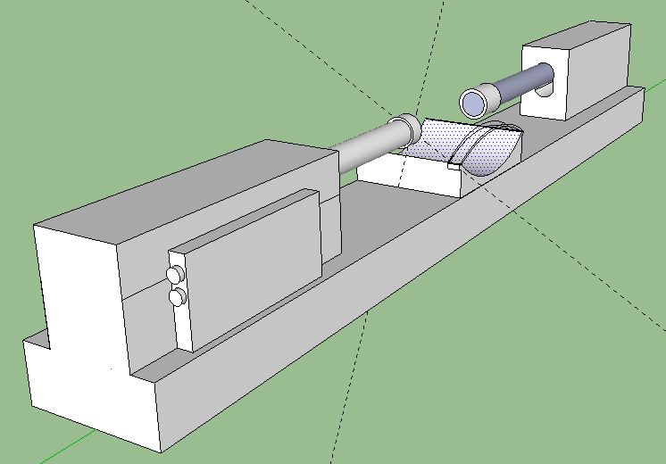
This post is to state that I wanted to do a redesign of the old idea, which is to take two linear actuators, align them up, and the two ends of the actuators would push inward loading the synovial joints. Refer to the old picture I drew using Google Sketch Up.
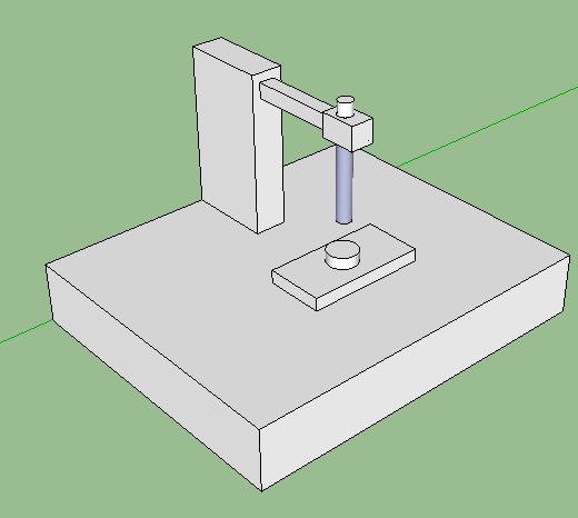
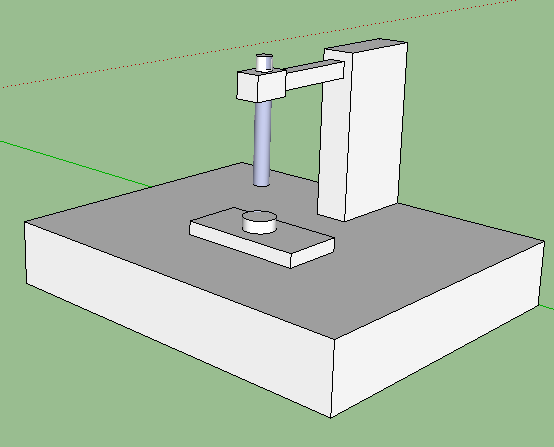
Now look at the design that Yokota (with Tanaka) is proposing. It is much simpler in design because instead of two actuators or machines that is pushing down and up in a sinusoidal manner, there is actually just one lever that is moving up and down in a certain frequency.
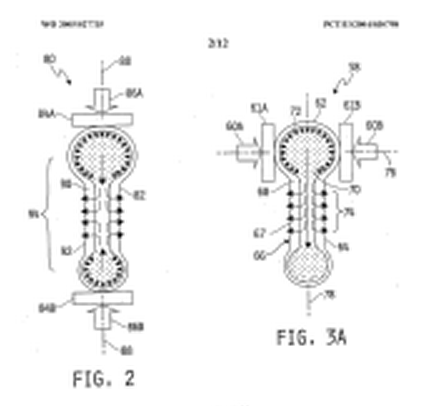
The idea is that we just use one movable piece loading on one side, and hold the other side of the synovial joint in place using a firm board or surface so that the joint can’t move as a result of being loaded.
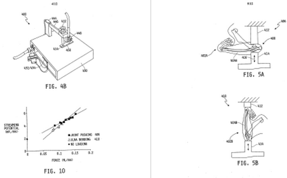
The first picture is showing that we want to be loading the bones in the lateral direction from the axis direction of the long bones. The side of the epiphysis is being pushed down.
I am looking at the lever that is pushing down on the joint and I am questioning whether it is even necessary to making the loading mechanical. Would it just be simpler if we did it using human arm strength, pushing down on the metal piece that is doing the loading?
I used to design 3-D Objects using the Mechanical Engineering softwares Solidworks, 3DS MAX, and Autocad but it is still rather difficult for me to figure out what exactly the design should look like in a 3-D way.
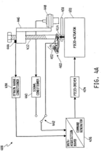
The writing on the patent is extremely hard for me to read. It seems to say that the bottom part is a piezo-actuator, which makes sense. The bones themselves have piezoelectric properties.
When the level is pressed down on the bone, I am guessing that the circuit is fully closed, leading to a small amount of current being run through the device, giving a slight electrical signal to the bone/epiphysis of the loaded area. This might be what Yokota means when he is saying that the bones as piezo-electric material will react in some way to remodel themselves form the electrical signal.
However using the Google SketchUp, since it is free and I don’t have a Solidworks or AutoCad license anymore, I have only been able to so far in the simplified design. I can not go any farther since I don’t exactly know what I am seeing or reading. The 3-D design I have posted below is all that I can do. It will eventually save money at least for the initial cost of the building of say the first prototype.